
For various projects of mine I need to be able to synthesize sound, so I decided to take a quick dabble in the realm of Digital Signal Processing. I mean, how hard could it be, right?
After some fooling around with the Sampled Audio Subsystem of the Java Virtual Machine I was able to hear sinusoidal waveforms of various frequencies from my speakers, and I was starting to think that I am probably almost done, until I tried to play square waveforms. That's when I realized that I had barely scratched the surface. The square waveforms sounded pretty awful at any frequency, and especially at high octaves they sounded like random notes. Triangular waveforms, sawtooth waveforms, really anything except sinusoidal waveforms all suffered from the same problem.
A bit of googling around soon revealed the name of the source of my troubles: aliasing.
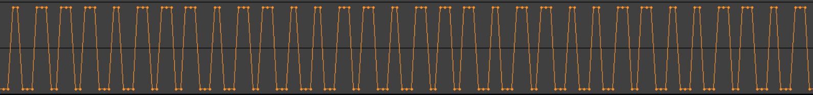
|
| A naïvely sampled square wave, exhibiting a bad case of aliasing. Note how some of the peaks and valleys consist of 3 samples, while some consist of only 2 samples. |
(Useful pre-reading: About these papers)
The Wikipedia article about aliasing (https://en.wikipedia.org/wiki/Aliasing) has a lot to say, but in my own words, aliasing is a phenomenon that occurs when we try to digitally approximate an analog signal by naïvely generating samples that try to match as closely as possible the approximated signal. It occurs with graphics, when we try to approximate an ideal line using pixels of a certain discrete size, and it also occurs with sound, when we try to approximate an ideal waveform using samples at certain discrete intervals. Aliasing essentially means that our digital approximation will not only deviate from the ideal signal, but it will actually deviate by varying degrees along the signal, and these varying degrees of deviation will exhibit cycles of repetition. These repetitive variations in the deviation are, more often than not, perceptible by our senses, and rather unpleasant.
When looking for a solution to the problem of aliasing in audio, the first port of call is of course the various Sound Engineering and Digital Signal Processing forums, like dsp.stackexchange.com or kvraudio.com/forum. Unfortunately, folks involved with audio tend to speak an exotic language which consists of the articles and prepositions of English, with nothing but utterly incomprehensible jargon in-between. They like to talk about harmonics, and band-limited waves, and band-pass filters, and Nyquist frequencies, and Lagrange interpolations, and DC compensations, and all sorts of mumbo jumbo that seems, at least to me, to bear absolutely no relation to buffers containing floating point sample values, which is all that my little world consists of. This makes it very hard for someone who is not a sound engineer to obtain useful information and apply it to solve problems.
Furthermore, some of the jargon that DSP folks use refers to concepts that are computationally expensive to the point of being inapplicable to any practical problem. I found a certain solution here: https://www.nayuki.io/page/band-limited-square-waves which even includes source code in Java, and it does indeed sound awesome: all undesirable effects are gone, and each note sounds pure and at the right frequency. Unfortunately, this solution is an application of the well known and hopelessly theoretical approach to square waveform generation by means of adding up an infinite number of sine waves, so it is extremely computationally expensive and therefore completely useless for any real-world purpose.
The fact that a square waveform can be generated using the infinite sine wave superposition method may, in some utterly roundabout way, have some application in something I guess, but as far as the real world is concerned, it is nothing more than a curiosity; an "interesting to know" factoid, about as useful as the factoid which says that the tomato is technically a fruit rather than a vegetable.
Then I managed to find floating on the interwebz a very promising solution that goes by the bizarre name of "PolyBLEP". It came with C++ code which I ported to Java. The C++ code can be found here: https://github.com/martinfinke/PolyBLEP and discussion by its author, Martin Finke, is here: http://www.martin-finke.de/blog/articles/audio-plugins-018-polyblep-oscillator Later I also came across a library called "DaisySP", which contains more or less the same code.
Even though a square waveform generated using Polyblep looks anything but square, it sounds exactly right, and it does not suffer from aliasing. Also, Polyblep is not too expensive computationally.
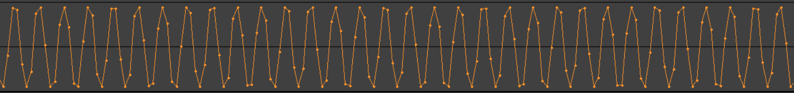
|
| A square waveform generated using PolyBLEP. |
Unfortunately, I have a few problems with Polyblep:
- The math is just voodoo magic to me; I do not have the slightest clue as to how it works.
- The code is specifically written to generate a number of predefined waveforms; it will not work with just any waveform.
- My inability to understand the math means that I cannot adapt the algorithm to work with any waveform.
So, I decided to ask for help.
I created a post on stackoverflow: "Efficient generation of sampled waveforms without aliasing artifacts" https://stackoverflow.com/q/66943566/773113 and a post on the KVR forum: "Call for help regarding anti-aliasing" https://www.kvraudio.com/forum/viewtopic.php?p=8370848
A number of kind people posted answers, and I did learn some useful things from these answers; unfortunately, it was not enough to help me solve my problem, and so far, nobody has volunteered to open up a conversation with me.
Also, some of the people who tried to enlighten me, although undoubtedly well intended, and although admittedly quite lucid in their explanations, seem to suffer from delusions, or misconceptions at best. For example, I heard it being said that a good digitization of a square waveform that is free from aliasing is supposed to have wiggles right before and right after each cliff. These are the wiggles that are characteristically produced by their favorite preposterous method for square waveform generation, the infinite sine superposition method, which as I have already explained, is useless. I came across people who are under the impression that this is what Polyblep does. Well, sorry, but it does not.
I may not fully understand how Polyblep works, but I have seen its results on a wave editor, and there most definitely exist no such wiggles. And there could be no such wiggles, because Polyblep only operates on one, maximum two samples before and after each cliff, regardless of frequency and sampling rate, and you need several samples in order to produce wiggles. To put it in other words, generating such wiggles would necessarily be computationally expensive, and Polyblep does not do anything that is anywhere near expensive enough. And yet, Polyblep sounds quite good without any such wiggles, which proves that the wiggles are unnecessary.
It does not take a genius to figure that out, because these wiggles are tiny compared to one entire cycle of a wave, which means that they represent frequencies that are far beyond the audible range, which in turn means that they could not possibly have any effect on anything whatsoever. These wiggles are just a relic from the analog times, and yet people keep superstitiously referring to them at this digital day and age.
So, I decided to try and tackle the problem all by myself, reasoning that it is just buffers containing floating point sample values, so the solution should come from the realm of algebra and geometry, without the need for lofty DSP concepts, nor deep math.
First of all, let us state the goal:
I want to be able to describe any waveform using what I like to call the "Unit Wave". This is a series of connected straight line segments in two dimensions, where Y corresponds to amplitude and X corresponds to phase. Y varies between -1.0 and +1.0, while X varies from 0.0 to 1.0, and is of course non-decreasing. (In the future I might upgrade the concept from straight line segments to polynomial curve segments, but for now, straight line segments will do.)
A Unit Wave describes a single period of a certain waveform, irrespective of frequency or sampling rate. The idea is that for any waveform imaginable, one can construct a Unit Wave describing it or approximating it, and by repetitively sampling that Unit Wave, one should be able to generate a continuous stream of that waveform at any desired frequency and at any desired sampling rate. So, the Unit Wave is supposed to be the ultimate solution to the problem of synthetic waveform generation.
The trick is that the generated waveform must somehow come out anti-aliased.
First I had an idea which I decided to call "Slicing". (See Appendix A: The "Slicing" algorithm.) I had high hopes that slicing would provide a solution to the problem, but it did not. The resulting waveform sounded much better than the naïvely generated waveform, but it was not nearly as good as Polyblep: it still suffered from distinctly audible aliasing artifacts.
Then, I had another idea, which I called "Smoothing". (See Appendix B: The "Smoothing" algorithm.) The algorithm is not very well defined yet, and there are various features that can be found in waveforms that I am not sure how to handle, but it is pretty straightforward in the case of the square waveform, so I decided that for the time being I would experiment with only square waves. Again I had high hopes that Smoothing would provide a solution, and again I was let down, in exactly the same way: better than naïve, not nearly as good as Polyblep.
When I loaded all four waveforms (Naïve, Polyblep, Slicing, Smoothing) into a multitrack audio editor and saw them one below the other, I noticed that Slicing looked identical to Polyblep about half of the time, while the other half of the time it looked more like the naïve waveform, while Smoothing exhibited the same pattern: half the time right, half the time wrong. Then I made a startling discovery: when Slicing was right, Smoothing was wrong; and when Slicing was wrong, Smoothing was right.
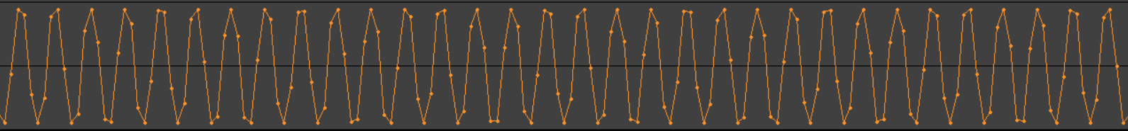
Of course, this immediately prompted me to try both Slicing and Smoothing cumulatively applied, and voila, the result was an excellent waveform, virtually indistinguishable from Polyblep both to the eye, and to the ear, and to the spectrum analyzer.
|
|
||
PolyBLEP
|
This alone should be causing some ruffling of feathers in the DSP community: in some corner of the world, some programmer with practically zero knowledge of DSP and calculus-level mathematics managed to produce results virtually identical to Polyblep using algorithms that he just empirically came up with, utilizing nothing but algebra and geometry, bypassing all their lofty theory and their indecipherable jargon.
Also, note that Polyblep is criticized as not being 100% accurate, so the difference between my results and Polyblep that can (barely) be observed using a spectrum analyzer might not necessarily be due to some inaccuracy of my algorithms; it may be due to some inaccuracy of Polyblep.
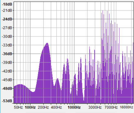
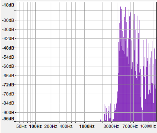
|
| Spectrum analysis of the naïvely sampled square waveform |

|
| Spectrum analysis of the same square waveform generated using PolyBLEP |
|
| Spectrum analysis of the same square waveform generated using Slicing + Smoothing. |
There is practically no visible difference between Polyblep and Slicing + Smoothing; the two plots look identical to such a degree that it is as if someone made a mistake and pasted the same image twice.
The (very subtle) differences become visible with the help of an animated gif:

|
| Animated gif showing the difference between PolyBLEP and Slicing+Smoothing |
Unfortunately, I am still faced with several problems:
- I have some idea as to why slicing produces good results only half of the time, but I am not sure yet how to go about fixing this.
- Smoothing is still not well defined; specifically, the only kind of waveform on which it will currently produce the intended results is the square waveform.
- I do not know why, even on the square waveform, smoothing produces good results only half of the time.
- I do not know why the half of the time that slicing produces good results is the exact opposite of the half of the time that smoothing produces good results. (It is just a fortuitous happenstance that this is so, because it allows me to obtain very good overall results by cumulatively applying both methods.)
- As a result of the above, I am not sure whether I should put further work into one of the two approaches, to make it work by itself, or whether I should continue in the direction of cumulatively applying both approaches. (Which still necessarily involves improving the as of yet incomplete smoothing method.)
- Adding to my dilemma, I am not sure whether I should continue at all in any of the above directions or whether I should instead try to construct a general-purpose implementation of Polyblep which works with any waveform.
These are my notes so far.
This document will be updated with developments.
Appendix A: The "Slicing" algorithm
Generating the samples that describe a waveform is a lot like sampling an analog signal using an Analog-To-Digital converter. The input to the converter is line segments that describe a wave, and the output is sample values. Of course we are talking about software here, so strictly speaking, there is nothing analog per se, but the input can be thought of as being analog in the sense that: a) we are using floating point values, and b) a line segment consists of an infinite number of points along a slope.
The naïve approach to digitizing an analog signal is to generate samples by reading the signal at discrete, infinitesimally narrow points in time. However, if you do this, you are guaranteed to experience aliasing. So instead, let us try something different: Instead of considering infinitesimally narrow points along the wave, let us consider entire slices of the wave, each slice as broad as one sampling period.
In other words, for each sample, let us calculate the surface area of a shape defined as follows:
- Along the x axis, it extends from the current sample time (x) until the next sample time (x+dx).
- Along the y axis, it extends from y=0 to the line given by the wave function f(x).
Let us then convert that measurement of area to a linear sample value by applying some kind of normalization.
Since the range of our sample values is from -1 to +1, this will involve an exotic notion of negative area, but that should not matter, it should all work out in the end.
It stands to reason that the normalization step should consist of dividing the computed wave slice surface area by the maximum slice surface area, which is the surface area of the rectangle with a height of 1 and width equal to dx. So, normalization is essentially just dividing by dx, or multiplying by 1/dx for those of us who are extremely performance-oriented.
Let us first try this approach with a sine wave, as a proof of concept. It has been a very long time since I was at the University, but luckily I still remember some of the basic principles of Calculus, so I know that the surface area between the curve described by the function y=f(x) and the line at y=0 is the integral of that function. The Calculus book says that the integral of sin(x) from x=x1 to x=x2 is cos(x1) - cos(x2). Therefore, to produce a sine wave using the wave slice approach, we need the following computation:
y = cos( 2π x1 ) - cos( 2π x2 ) / ((1/samplesPerWave) * 2π)
So I tried this, and the resulting waveform is exactly the same as the one produced by y=sin(x), so we are on a good path.
When dealing with line segments, things are even more simple: at each step, the surface whose area we want to compute is the trapezoid defined by one straight horizontal line at y=0, two parallel straight vertical lines at x and x+dx, and one straight slanted line from f(x) to f(x+dx). So, we do not even have to compute the area and then divide by dx, we can just take the midpoint of the slanted segment, which is ( f(x) + f(x+dx) ) / 2.
As I have already explained, the slicing approach is better than the naïve approach but not as good as Polyblep. The reason seems to be that it tends to reproduce many of the points of the original analog signal a bit too faithfully, and as I have already explained, faithful reproduction of the original signal is naïve. Specifically, when sampling a square wave at a rate of dx, near a cliff going up, it may happen that a slice will be considered right before and just barely including the cliff, and the next slice will be right after the cliff. Since the cliff will be at exactly the end of the first slice, it will have an infinitesimally small contribution to the computed surface area, so the first slice will measure nothing but flat valley before the cliff at -1.0, while the next slice will measure nothing but flat top after the cliff at +1.0, thereby reproducing the absolute hardness of the cliff, which is something that never happens with Polyblep. I am not sure yet how to go about mitigating this.
Appendix B: The "Smoothing" algorithm
It appears to me that aliasing occurs because the process of sampling at discrete time intervals is bound to sometimes catch, and sometimes miss, various features of a waveform. Take, for example, the peak of a triangular waveform. If a sample happens to be taken exactly at the peak, then no information will be lost. However, far more often, a sample will be taken before the peak, and the next sample will be taken after the peak. Furthermore, the two samples will almost never be equidistant from the peak; one of the samples will always be closer to the peak than the other, their relative distances from the peak will vary, and the variation will exhibit some periodicity, dependent upon the sampling rate and the frequency. This is bound to cause aliasing.
So, I am putting forth the hypothesis that if every feature of the waveform was at least as broad as one sampling period, then every feature of the waveform would be sampled at least once during each cycle of the waveform, and so there might be no aliasing.
Therefore, the question is: can we somehow pre-process a Unit Wave for a given sampling rate to ensure that each of its features is at least as broad as the sampling period?
Waveforms consisting of straight line segments can have the following kinds of features:
- A non-vertical line segment followed by another non-vertical line segment of a different slope but same slope sign. (For example, two successive segments on the same upwards or downwards slope of a sine wave that is being approximated using line segments.)
- A non-vertical line segment followed by another non-vertical line segment with a slope of the opposite sign. (For example, the segment right before the peak of a triangular wave, and the segment right after the peak.)
- A non-vertical line segment followed by a vertical line segment. (For example, a slope followed by a cliff on a sawtooth wave.)
- A vertical line segment followed by a non-vertical line segment. (For example, a cliff followed by a valley on a square wave.)
It is yet unclear to me exactly how to go about pre-processing these cases, but at least I know what to do in the case of a horizontal line segment followed by a vertical line segment followed by another horizontal line segment, which is the one and only feature found on the square waveform.
The idea is to displace the top of the vertical line segment horizontally in one direction by dx/2, and the bottom of the vertical line in the other direction by another dx/2.
This will turn the vertical line segment into a sloped line segment whose projection on the x axis has a length of dx, and will ensure that some point along this segment will always be sampled on each cycle of the waveform.
Unfortunately, this approach suffers from various problems. Even though some strategy could be devised as to how to handle each type of feature that can be found along a waveform, it is entirely unclear to me what should happen in cases where shifting a point to the left or to the right makes it bump a previous or next point belonging to the preceding or succeeding feature of the waveform.
No comments:
Post a Comment